MEASUREMENT OF LOCAL VOID FRACTION AT ELEVATED TEMPERATURE AND PRESSURE
Presented at:
Third World Conference on Experimental Heat Transfer, Fluid Mechanics
and Thermodynamics
Honolulu, Hawaii, USA, 31 October-5 November, 1993
D. Duncan and T.A. Trabold
General Electric Company, P.O. Box 1072, Schenectady, NY 12301 U.S.A.
C.L. Mohr and M.K. Berrett
Mohr and Associates, 1440 Agnes Street, Richland, WA 99352 U.S.A.
ABSTRACT
Significant advances have recently been made in analytical and computational methods for the prediction of local thermal-hydraulic conditions in gas-liquid two-phase flows. There is, however, a need for extensive experimental data, for the dual purposes of constitutive relation development and code qualification. This is especially true of systems involving noncircular geometries and/or extreme flow conditions for which little, if any, applicable information exists in the open literature. For the tests described in the present paper, a novel electrical probe has been applied to measure the void fraction in atmospheric pressure air/water flows, and steam/water mixtures at high temperature and pressure. The data acquired in the latter experiments are compared with the results of a one- dimensional two-fluid computational analysis.
INTRODUCTION
Over the past several decades, much effort has been devoted to improving computational methods for the prediction of local thermal-hydraulic conditions in gas/liquid two-phase flow. Recent advances in computational capability have, however, resulted in an imbalance between our ability to solve the complicated conservation equations and our ability to measure physical parameters which describe interactions between the phases. It is now apparent that additional detailed experimental data are required, both for the purpose of formulating the required constitutive relations and for code qualification. General Electric is presently developing computational methods based on a rigorous two-fluid formulation which has become the impetus behind a comprehensive program to simultaneously develop two-phase flow measurement techniques for high-pressure steam/water applications. Of the various parameters which need to be measured, the local void fraction is of primary interest for defining the two-phase flow environment. As used in the present paper, the void fraction is defined as the volume occupied by the gas phase relative to that of the two-phase mixture:
$$\alpha = \frac{V_g}{V_{mix}} = \frac{V_g}{V_g + V_l}$$ Equation 1
It is usual, with appropriate averaging, for the void fraction to be considered as a space-time variable and so the volumes in Eq. (1) become differential[1].
As documented in several reviews (e.g., Brockett and Johnson[2]; Hsu [3]; Delhaye[4]; Mayinger[5]; Snoek[6]; Yokobori et al. [7]), a number of techniques for local void fraction measurement have been used with varying degrees of success. These techniques generally have limitations which make them unsuitable for transient two-phase flows in which the local time-varying data are of interest, and where the temperatures, pressures and water chemistries make them impossible to apply. For example, gamma densitometry is limited by the long counting times and rather expensive equipment. Additionally, there are restrictions on the handling of this equipment due to the radiation source. Other methods such as the optical probe and hot-film anemometer have been used for local measurements (Cartellier and Achard[8]), but are not suitable for high-pressure and temperature conditions. This is especially true in applications in which the working fluid can be very corrosive to the sensitive portion of these types of devices.
Electrical instrumentation techniques are particularly attractive for local void fraction measurements, due to their ability to resolve high frequency changes in the two-phase flow field. The general principle of operation of electrical void fraction probes is based on the difference in the electrical properties between the liquid and vapor phases. As outlined by Hardy and Hylton[9], the admittance (inverse of impedance), Y, of a two-phase mixture can be described by a complex number:
$$Y_{mix} = G_{mix} + j\omega C_{mix} = |Y|e^{j\Theta}$$ Equation 2
whose real part is the conductance G and whose imaginary part is the susceptance ωC, where C is the capacitance, ω is the angular frequency of excitation and Θ is the phase angle. The two-phase mixture conductance and capacitance for a fluid like water, where the conductivity and the dielectric constant of the liquid are much greater than those of the corresponding vapor phase, can be expressed as
$$G_{mix} = \frac{\gamma_{m}}{B}$$ Equation 3
$$C_{mix} = \frac{\epsilon_{m}}{B}$$ Equation 4
where γm is the average mixture conductivity, εm is the average mixture capacitance, and B is a constant determined by the geometry of the electrode. In general, an electrical impedance-type probe measures the magnitude and phase of the admittance, which in turn permits the determination of γm and εm which can be related to void fraction through calibration.
A variety of probe geometries has been applied, including those in which the ground and emitter are placed opposite test section walls, and those which are completely immersed in the two-phase flow. Depending on tile system configuration, the impedance will be dominated by conductance (conductivity probe), capacitance (capacitance probe) or both (impedance probe). In general, it is desirable to operate at a high enough frequency to ensure the domination of the capacitance term because the liquid conductivity is a strong function of temperature and ion concentration whereas the capacitance is not significantly affected by these factors. The impedance-type probes can generally be used for both steady and transient measurements due to their virtually instantaneous response. Accuracy is adequate for low void fractions when the water chemistry is stable, but may be limited at extremely small vapor volume fractions when the mixture impedance is close to that of the pure liquid. The probe sensitivity can be expected to improve with increasing α, but at very high void fractions, accuracy often decreases since the measured void fraction is dependent on the distribution of voids and entrained liquid in the neighborhood of the active element. The probe and signal processing costs are relatively moderate; however, application in a high pressure steam/water environment is complicated by the required mechanical penetration and the fact that the electrical insulators which support the electrodes might not be able to survive for long term measurements.
The impedance-type probes have been used extensively for void fraction measurement and a number of different electrode geometries have been investigated. General problems encountered with electrical sensors include phase distortion, electrochemical effects, nonrepresentative conductive paths, nonlinear response due to the effect of flow regime, probe wettability and surface tension. To minimize these problems, it is required that the sensor and data acquisition technique be designed and calibrated specifically for the desired measurement. Also, most instruments lose their sensitivity when the sensing device is positioned at a significant distance from the signal acquisition hardware or when there is a change in the electrical properties of the fluid. This is primarily due to either the increase in the signal-to-noise ratio caused by increasing the length of the transmission cable, or significant changes in dielectric constant or resistance of the fluid, both of which decrease the ability to resolve the signal.
A new proprietary electrical method which overcomes these deficiencies, hereafter referred to as the Electric Field Perturbation (EFP) technique, has been developed by Mohr and Associates. The probe can be used in a variety of applications in high temperature and chemical environments (high conductivity, mildly corrosive), allowing remote measurements to be made over extended periods of time. For purposes of the present study, several EFP probes have been adapted by Mohr and Associates to measure the local void fraction in various water chemistries at high temperature and pressure.
A brief description of the test facilities and some of the most significant results of experiments performed in an air/water flow loop and a pressurized autoclave system are given below. These results demonstrate the potential usefulness of the measurement technique in improving analytical models and computational methods, as well as offering insight into the physical behavior of two-phase flows under severe thermal-hydraulic conditions.
AIR/WATER EXPERIMENTS
Test Facility and Measurement System
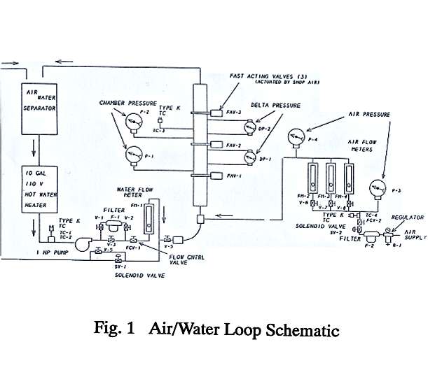
Figure 1. Air/Water Loop Schematic
A series of preliminary tests was performed in an air/ water flow loop (Figure 1), for the early qualification of the EFP probe. The loop consisted of a heated water tank, water pump, vertical transparent cast acrylic test section and an air/water separator. The test section was separated into two modules by three fast-acting valves which were used to quickly (in about 0.1 sec) trap the two-phase flow mixture. The regulated house air supply was metered with a set of three rotameters, while a single rotameter placed downstream of the pump was used to meter the water flow. An air-water mixing chamber was located at the inlet of the test section. For a given set of air and water flowrates, the two-phase flow field could be altered by varying the method of air injection. When the air was introduced by means of a manifold, the bubbles formed were generally larger, less frequent and not uniformly distributed across the test section width. Conversely, with air injection through a soapstone, the smaller bubbles were rather uniform in both size and distribution. The latter configuration was considered to more closely model the expected two-phase flow structure in high pressure steam/water applications. The loop instrumentation included differential pressure (DP) cells and pressure gages to monitor both the absolute pressure and the pressure drop in tile upper and lower parts of the test section. The EFP probe, 12.7 mm wide and 50.8 mm long in the streamwise dimension, was positioned at the center plane of the upper section of the 63.5 X 6.35 mm cross-section rectangular flow duct, between fast-acting valves (FAVs) # 2 and 3 approximately 1600 mm downstream from the duct entrance. The probe was completely immersed in the two-phase flow field, and therefore the measured void fraction was a volume average over the length and width of the probe and cross section of the flow duct. Since under the conditions used in these experiments the bubble diameter was significantly larger than what is expected in a pressurized water system, a more comparable two-phase flow environment was simulated by adding a small amount of soap to lower the water surface tension in all tests.
Results and Discussion
The validation of a new measurement technique requires the existence of a standard. However, it is generally difficult to qualify measurements made with a local void fraction device since no convenient standard exists. The fast-acting valves allow, by measuring the relative lengths of the tripped gas and liquid columns, a direct measurement of the spatially averaged void fraction. A local measurement, such as that from the EFP probe, can be validated against a spatially averaged measurement only for flow conditions in which the vapor volumes are uniformly distributed in the test section. A second way to validate the results of the EFP probe is to compare them with the void fraction calculated from the differential pressure measurement. This comparison, however, can be made only for a limited range of flow conditions (low liquid and air flows) where buoyancy forces are predominant.

Figure 2. Air/Water Test Results (Various Flow Regimes)
The EFP void fraction probe was tested and performed well in air/water mixtures for a wide range of flowrates (0 - 930 kg/hr water flow and 0 - 285 standard liters/min air flow). As illustrated in Figure 2 for a single liquid mass flowrate, the variation of measured local void fraction with air volumetric flowrate follows the expected trend, and provided strong evidence that the EFP probe is capable of acquiring data in various flow regimes. However, the probe performance was validated only for a bubbly flow regime (0 - 18 kg/hr water flow, 0 - 3.4 standard liters/min air flow). This was the only test condition where a uniform, buoyancy dominated flow could be obtained. The EFP probe qualification data for a water flow of 18 kg/hr are presented in Figure 3.
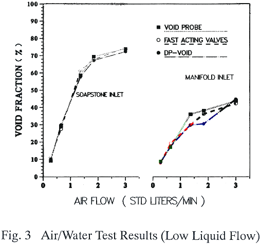
Figure 3. Air/Water Test Results (Low Liquid Flow)
The void fraction measured by the probe, fast-acting valves and the ΔP cell are shown as a function of the air flowrate for both air inlet mixing configurations. The experiments were run by keeping the water flow constant and varying the gas flow from 0 to 3.0 standard liters/min. When the air was introduced through the soapstone (smaller, well distributed bubbles) the void fraction measured by the EFP probe compares very well with the results obtained from both the fast-acting valves and ΔP cell; relatively good agreement was obtained even when the air was injected through the manifold. It is interesting that the EFP probe showed, as theoretically expected, a lower void fraction when larger bubbles were present due to the increased bubble rise velocity. For larger gas flows, the flow regime changed from bubbly to churn-turbulent. Under these conditions the local measurement could no longer be validated by a spatially averaged measurement from the fast-acting valves because the large unsteady bubbles were not uniformly distributed in the test section. Also, in this flow regime the friction forces are significant and the ΔP measurement cannot be used as a standard.
STEAM/WATER EXPERIMENTS
The successful qualification of the EFP probe in the air/water bubbly flow did not guarantee that it would work in the intended high-pressure, high temperature, high pH steam/water application. In a two-phase flow environment, the electrical properties of the liquid change with temperature. Therefore, it was necessary to apply a temperature correction to the correlation between probe signal and void fraction obtained from air/water data. An additional concern in the application of the EFP probe in steam/water was that the high electrical conductivity of the solution could result in loss of signal. It was therefore considered imperative to perform an additional series of tests to validate the EFP probe in a pressurized boiling autoclave.
Test Facility and Measurement System
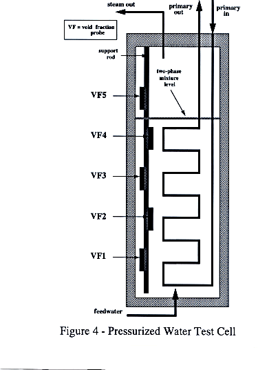
Figure 4. Pressurized Water Test Cell
The test facility used to evaluate the performance of the EFP probe in a pressurized steam/water environment is shown schematically in Figure 4. It consisted of an autoclave heated by a primary (high-pressure water) tube array. The total heat input was controlled by varying the primary side flowrate and inlet temperature. The autoclave basically is a heat exchanger with the secondary side in a pool boiling (low phase velocities) configuration. The interface between the two-phase mixture and pure steam was kept constant by a feedwater controller. This controller matched the subcooled feedwater flow introduced at the bottom of the autoclave with the outlet steam flow. The test facility was instrumented to monitor primary water inlet and outlet temperatures and flowrate, feedwater temperature and flowrate and two-phase mixture level. Additional instrumentation was installed to monitor steam flowrate and the steam and two-phase mixture temperatures on the secondary side. Experiments were performed using water (Solution A) with electrical conductivity of 8 µmho/cm and pH = 8.8, and Solution B with conductivity of 500 µmho/cm, and pH of approximately 10.8.
Five void fraction probes, 76.2 mm long in the vertical dimension, were mounted with equal spacing on a rod and inserted into the test cell as indicated in Figure 4. As the water level was varied, the position of the probes relative to the interface between two-phase mixture and steam changed, resulting in different local void fraction conditions and boiling characteristics. The probes were connected to a signal processing unit controlled by a host computer. Data acquisition and analysis software has been developed for IBM-clone 386 and 486 PC systems, as well as HP workstations.
One-Dimensional Computational Analysis
In order to gain some insight as to how the void fraction can be expected to vary with axial (Z) position (along the EFP probe array) within the autoclave, a one-dimensional computational analysis was performed. This was considered to be an integral part of the void fraction probe data analysis since the variation of bubble size, which would be expected to affect the local thermal-hydraulic conditions, was not determined experimentally. Also, the elevated temperature and pressure conditions encountered in these experiments made it virtually impossible to perform a concomitant measurement which could provide a means for evaluating the probe's performance. A computer code was employed in which the following equations for conservation of mass, energy and momentum, respectively, were solved:
$$\frac{dG}{dZ} = 0$$ Equation 5
$$\frac{dE}{dZ} = q$$ Equation 6
$$\frac{1}{2}\alpha\rho_{g}\frac{d(U_{g}^{2})}{dZ} = \alpha\frac{d\Delta P}{dZ} - \alpha\rho_{g}g - F_{I}U_{r}^{2}$$ Equation 7
where the axial pressure drop gradient ( dΔP / dZ) is a combination of contributions due to elevation ( ΔPel ), acceleration ( ΔPacc ) and friction ( ΔPƒr ):
$$\Delta P_{el} = \int_{0}^{L} \rho_{m}g dZ$$ Equation 8
$$\Delta P_{acc} = M_{out} - M_{in}$$ Equation 9
$$\Delta P_{fr} = \int_{0}^{L} \frac{U_{l}}{|U_{l}|} \frac{f}{2D_{H}} |M| dZ$$ Equation 10
Note that since a one-dimensional formulation is used, the computed void fractions are actually spatial averages over horizontal "slices" of the modeled autoclave; no radial void fraction distributions are calculated. If the vapor-phase is considered to consist of dispersed spherical bubbles, the interfacial shear coefficient ( FI ) may be expressed as
$$F_{I} = \frac{3\alpha C_{D}\rho_{l}}{4D_{b}}$$ Equation 11
where ρl, CD and Db are, respectively, the liquid density, drag coefficient and bubble diameter. The drag coefficient was set equal to 0.44 for all computations, whereas the bubble diameter was treated as a variable parameter for the purpose of comparison between experimentally and computationally determined void fractions. To determine an approximate range over which the specified bubble diameter should be varied, the following correlations for bubble diameter at departure from a heated surface were applied:
Fritz[10]
$$D_{b} = C\beta \left[ \frac{2g_{c}\sigma}{g(\rho_{l} - \rho_{g})} \right]^{1/2}$$ Equation 12
where C was found experimentally to be 0.0148 for water bubbles and β corresponds to the contact angle which could vary from roughly 20 to 60 degrees;
Borishanskiy et al.[11]
$$D_{b} = \frac{0.00149}{P^{0.46}}$$ Equation 13
where Db and P have units of meters and bars, respectively. For saturated components at a pressure of about 4.1 MPa and over all contact angles, Eqs. (12) and (13) yielded bubble diameters from 0.25 to 2.3 mm. Since there was such a large variation in possible Db values estimated from these two empirical correlations, it was apparent that the computations should be run using range of bubble diameters. For purposes of the analysis, this range was chosen to be 0.2 to 2.5 mm.
Results and Discussion
The objectives of these tests were to demonstrate that the void fraction probe could function in a high-pressure steam/water environment, to provide data that could be compared with prior calculations and to help understand differences in the void friction distribution in the autoclave as a function of heat flux and flowrates. Additionally, the EFP probe's performance in a high conductivity water solution was also investigated. To achieve these objectives, two types of tests were performed.
The first set of experiments maintained a constant liquid level while the heat input was varied by changing the primary water temperature and/or flowrate. For this test series, each data point was acquired at a constant heat input. In the second set of experiments, the primary water conditions (heat input) were held constant while the liquid level was varied. Typical results from these sets of experiments are illustrated in Figures 5 and 6 respectively.
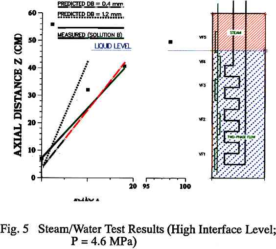
Figure 5. Steam/Water Test Results (High Interface Level; P = 5.6 MPa)
Figure 5 presents a comparison between the EFP probe measurements and a ID two-fluid model calculation in which the interfacial shear force (FI) was changed by specifying different bubble sizes. The test was run in Solution B under saturated conditions at 4.6 MPa (100% heat input) with the two-phase mixture level just barely contacting the bottom of void fraction probe VF5. Generally, the local void fraction increases with vertical position, although some variation from this trend is observed due to differences in probe proximity to the primary water tube. The probe VF2 was located close to the heating surface and measures a higher than average void fraction. The probe VF3, yielding a relatively low void fraction measurement, is located opposite the array and is shielded from the heated surface by the supporting rod. A linear regression of the void fraction data from EFP probes VF1 through VF4 correlates well with the ID analysis using an interfacial shear force based on 0.4 mm average diameter bubbles. Probe VF5, which for this test resided mostly in the steam space above the two-phase mixture interface, yielded a void fraction measurement of about 98%. The measured 2% liquid volume fraction is likely due to the frothing behavior of the liquid/steam interface.
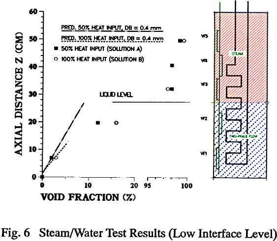
Figure 6. Steam/Water Test Results (Low Inteface Level)
Figure 6 compares the data for two test points from the second set of experiments (Solution B at 4.6 MPa and 100% heat input; Solution A at 5.3 MPa and 50% heat input) run with the two-phase mixture interface located low in the autoclave, beneath probe VF3. As expected, and predicted by the 1D model, the EFP probe data indicate that there is an increase in the local void fraction with increasing heat input. As mentioned above, the probe VF2 is located near the heating surface and will tend to measure a higher local void fraction. The measurements also show a distinct change in void fraction at the interface between two-phase mixture and steam. In fact, the froth level near the interface at EFP probe VF3 could easily be detected by the dynamic change in local void fraction indicated by the probe. Another very important finding was that the probes were able to detect slight differences in moisture carryover at the three highest measurement locations. For example, for the Solution A test at 50% heat input, probes VF3, VF4 and VF5 yielded local void fraction measurements of 98.0, 98.3 and 99.0%, respectively, indicating that the moisture carryover decreases away from the interface. As expected, there are no significant differences in data for 50 and 100% power in the steam space.
CONCLUSIONS
A novel electrical technique, the Electric Field Perturbation probe, his been applied to measure the local void fraction in various gas-liquid two-phase environments. For testing in vertical air/water flows through a rectangular duct, the data acquired with this device were validated with spatially averaged results obtained using fast-acting valve and differential pressure methods at low liquid flow- rates in the bubbly flow regime. Also, results obtained over the full range of gas and liquid flowrates indicate that the probe can potentially be used in all flow regimes. In the case of pressurized water two-phase flow, which is the actual physical environment for which the present study was undertaken, the EFP probe was able to detect small variations in void fraction over the entire range studied. At very high void fractions, subtle differences between pure saturated steam and slight amounts of moisture carry over near the two-phase mixture interface were measured. Also, for the lower void fraction region hear the bottom of the autoclave, differences in local void fraction due to heat input and probe proximity to the nucleate boiling source were detected.
From a practical standpoint, the measurement technique described in the present paper holds a great deal of promise since it was successfully applied at temperatures and pressures up to about 270°C and 5.3 MPa, and maintained its mechanical integrity in a pH = 10.8 environment. Also, the fact that the signal processing equipment was placed at an appreciable distance (4 to 5 m) from the sensitive portion of the probe indicates that its use in demanding research and industrial applications is possible. Future work is planned to perform a rigorous validation of the EFP void fraction probe under various flow conditions, using standard instrumentation such as the hot-wire anemometer and gamma densitometer. Also, the application of this device for flow regime identification through analysis of the output signal will be thoroughly investigated.
NOMENCLATURE
| C | capacitance, farad |
| CD | drag coefficient, dimensionless |
| Db | bubble diameter, m |
| DH | hydraulic diameter, m |
| E | energy, kJ/(m s) |
| ƒ | friction factor, dimensionless |
| FI | interfacial shear coefficient, kg/m4 |
| g | gravitational acceleration, m/s |
| G | conductance, mho; or mass flow, kg/(m s) |
| M | momentum flux, N/m2 |
| P | absolute pressure, N/m2 |
| ΔP | pressure drop, N/m2 |
| q | heat flux, W/m2 |
| U | phase velocity, m/s |
| Ur | relative velocity, i.e., Ug - Ul, m/s |
| V | volume, m3 |
| Y | admittance, mho |
| Z | axial (vertical) position, m |
Greek Symbols
| α | void fraction, dimensionless |
| β | contact angle, dimensionless |
| ε | capacitance, farad/cm |
| γ | conductivity, mho/cm |
| Θ | phase angle, dimensionless |
| ρ | density, kg/m3 |
| σ | surface tension, N/m |
| ω | angular frequency, Hz |
Subscripts
| g | gas phase |
| l | liquid phase |
| m,mix | two-phase mixture |
REFERENCES
- Lahey, R.T., Jr., Ed., Boiling Heat Transfer - Modem Developments and Advances, Elsevier Science Publishers, Amsterdam, 1992.
- Brockett, G.F., and Johnson, R., Single-Phase and Two-Phase Flow Measurement Techniques for Reactor Safety Studies, EPRI Report NP-195, July 1976.
- Hsu, Y.Y., Ed., Two-Phase Flow Instrumentation Review Group Meeting, U.S. Nuclear Regulatory Commission Report NUREG-0375, March 1978.
- Delhaye, J.M., Recent Advances in Two-Phase Flow Instrumentation, 8th International Heat Transfer Conference, Vol. 1, pp. 215-226, Hemisphere Publishing Company, New York, 1986.
- Mayinger, F., Modern Noninvasive Measuring Techniques for Transient Two-Phase Flow, Transient Phenomena in Multilphase Flow_ N.H. Afgan, Ed., pp. 901-922, Hemisphere Publishing Company, New York, 1988.
- Snoek, C.W., A Review of Recent Advances in Multiphase Flow Measurements and Methods, Experimental Heat Transfer, Fluid Mechanics, and Thermodynamics, R.K. Shah, E.N. Ganic, and K.T. Yang, Eds., Elsevier Science Publishers, pp. 59-71, 1988.
- Yokobori, S., lshizuka, T., and Ozaki, O., Recent Progress of Nuclear Thermal-Hydraulic Measurement Techniques, ASME/JSME Joint Thermal Engineering Conference, Volume 2, pp. 147-152, ASME, New York, 1991.
- Cartellier, A., and Achard, J.L., Local Phase Detection Probes in Fluid/Fluid Two-Phase Flows, Rev. Sci. lnstrum. 62, 279-303, 1991.
- Hardy, J.E., and Hylton, J.O., Electrical Impedance String Probes for Two-Phase Void and Velocity Measurements, Int..J.Multiphase Flow, 10, 541-556,1984.
- Fritz, W., Maximum Volume of Vapor Bubbles, Phys. Z., 36, 379, 1935.
- Borishanskiy, V.M., et al., "Correlation of Data on Heat Transfer in, and Elementary Characteristics of Nucleate Boiling Mechanism," Heat Transfer - Soviet Research, Vol. 13, 100, 1981.
