Aerospace Maintenance Council Competition 2026
This will be a troubleshooting task. The objective will be to determine and locate bad antenna components, bad engine harness components, and bad cable terminations.
Teams will be presented with problematic multi-component cable assemblies and be responsible for locating and identifying failure points using high-resolution TDR data. Faults may be intermittent, requiring the team to perform intermittent fault detection and location.
Competitors Required
- 1
References
Tools, Equipment, and Materials Provided
- CT100B Time Domain Reflectometer
- CT100-AK-BNC RF connector Kit
- CT100-AK-PSP MOHR MIL-DTL-38999 adapter kit
Scoring
Scores will be calculated according to the AMC score sheet. Additional penalties may be assessed for nonperformance of best practices.
Test 1: Identify bad antenna components
- Discharge static from Antenna Connector A (known good)
- Select appropriate cabling and adapters for identified cable/termination.
- Connect appropriate cabling to Device-Under-Test (DUT)
- Connect cable and DUT to CT100 TDR
- Press Orange Autofit button on CT100. CT100 will bracket entire cable length
-
Create high-resolution waveform of known-good sample
- Press the CT100 "Scan" button
- Discharge static from Antenna Connector B (known bad)
- Connect appropriate cabling to DUT
- Connect cable and DUT to CT100 TDR
- Perform Autofit if needed
-
Analyze Waveform differences between live trace (white) and known good trace
(red)
- Look for any differences in amplitude between waveforms (impedance irregularities) between connection point and antenna.
- Adjust cursors and scale as necessary to analyze waveform at higher gain.
- Move active cursor to fault location and notify judge
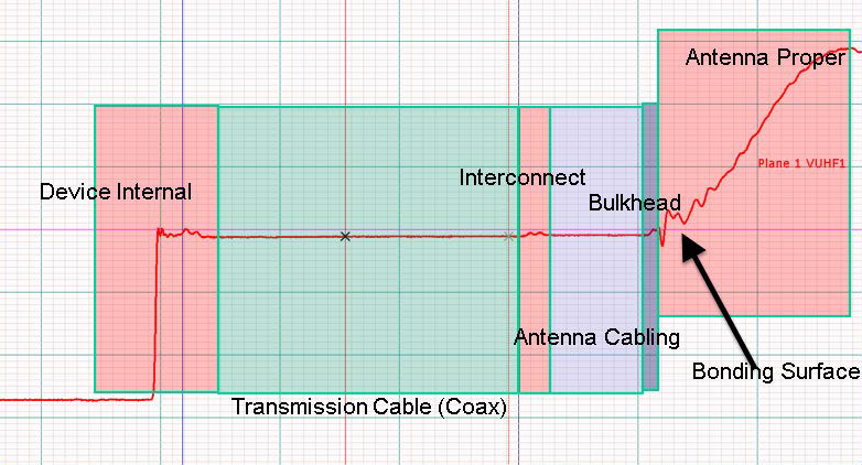
Test 1 Reference: Typical antenna installation
Test 2: Identify bad engine harness (incorrect cable impedance)
- Discharge static from Harness A (known good)
- Select appropriate cabling and adapters for identified cable/termination.
- Connect appropriate cabling to Device-Under-Test (DUT)
- Connect cable and DUT to CT100 TDR
- Press Orange Autofit button on CT100. CT100 will bracket entire cable length
- Create high-resolution waveform of known-good sample
- Press the CT100 "Scan" button
- Discharge static from Harness B (known bad)
- Connect appropriate cabling to DUT
- Connect cable and DUT to CT100 TDR
- Perform Autofit if needed
- Analyze Waveform differences between live trace (white) and known good trace (red)
- Look for any differences in amplitude between waveforms (impedance irregularities) between connection point and antenna.
- Adjust cursors and scale as necessary to analyze waveform at higher gain.
- Move active cursor to fault location and notify judge
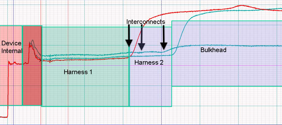
Test 2 Reference: Multi-part cable harness and interconnects
Test 3: Identify bad connector or cable kink
Judge will identify connector with known intermittent fault.
- Select appropriate cabling and adapters for identified cable/termination.
- Discharge static from identified connector
- Connect appropriate cabling to Device-Under-Test (DUT)
- Connect cable and DUT to CT100 TDR
- Perform Autofit if needed
- Analyze Waveform
- Perform Envelope Plot to start intermittent Fault detection:
- Press the CT100 Blue button until the Main Menu appears.
- Select "Envelope Plot"
- An envelope plot will appear on screen and identify any impedance changes in real-time.
- Reset the Envelope Plot as needed if changes are made to scale or position.
- Physically manipulate the DUT (shake) to locate and quantify intermittent faults. Distance to intermittent fault measurements can be made by moving the active cursor to the regions where major impedance changes occur.
- Move active cursor to fault location and notify judge
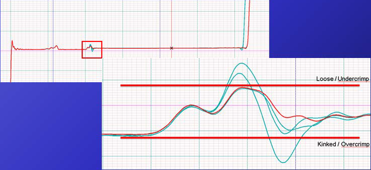
Test 3 Reference: Envelope Plot showing Pass/Fail impedances for 50ohm coaxial interconnect
VERTICON 2026
Georgia World Congress Center285 Andrew Young International Boulevard Northwest
Atlanta, GA 30313
Dates
March 9-11, 2026
Exhibition
B8737
Competition
B8834
MRO Americas 2026
Orange County Convention Center9800 International Drive
Orlando, FL 32819
Dates
April 20-23, 2026
Exhibition
4676
Competition
4766